Power gain of antenna equals directive gain in VHF and UHF range if and only if efficiency of the antenna is __________ .
-
0.25 -
0.5 -
0.75 -
1
The logic function implemented by the following circuit at the terminal OUT is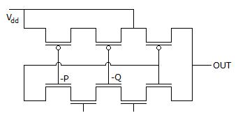
-
P NOR Q -
P NAND Q -
P OR Q -
P AND Q
Consider the Schmitt trigger circuit shown below. A triangular wave which goes from -V toV is applied to the inverting input of the op-amp. Assume that the output of the op-amp moves from +V to -V. The voltage at the non-inverting switches between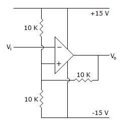
-
-12 V and +12 V -
-7.5 V and +7.5 V -
-5 V and +5 V -
0 V and 5 V
For the power amplifier circuit shown below, the maximum power dissipated by both output transistor is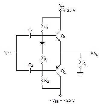
-
9.66 W -
30.11 W -
31.66 W -
33.66 W
The Boolean function realized by the logic circuit shown is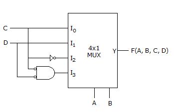
-
F = Σm(0, 1, 3, 5, 9, 10, 14) -
F = Σm(2, 3, 5, 7, 8, 12, 13) -
F = Σm(1, 2, 4, 5, 11, 14, 15) -
F = Σm(2, 3, 5, 7, 8, 9, 12)
Find equivalent capacitance if each capacitance is 2 F.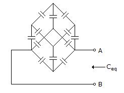
-
5/12 F -
12/5 F -
6/5 F -
5/6 F
The impulse response h(t) of a linear invariant continuous time system is given by h(t) = exp (- 2t) u(t), where u(t) denotes the unit step function. The output of this system to the sinusoidal input x(t) = 2cos(2t) for all time t, is
-
0 -
2-0.25 cos (2t - 0.125p) -
2-0.5 cos (2t - 0.125p) -
2-0.5 cos (2t - 0.25p)
Find RAB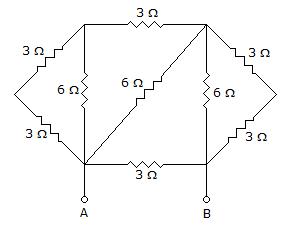
-
2 Ω -
1.5 Ω -
3 Ω -
None of the above
Find RL for maximum power transfer.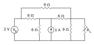
-
3 Ω -
1.125 Ω -
4.1785 Ω -
None of these
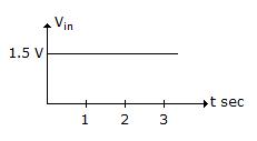
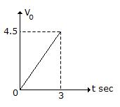
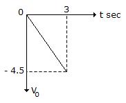
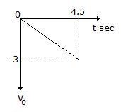
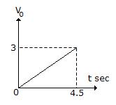
For a integrator circuit, Ri =KΩ, CF =μF. The input is a step dc voltage as shown below. Its output will be
AkHz carrier wave modulatedatHz is applied to a resonant circuit tuned to a carrier frequency and having Q =What is the degree of modulation after transmission through this circuit?
-
0.40 -
0.20 -
0.27 -
0.54
In the circuit shown, all the transmission line sections are lossless. The Voltage Standing Wave Ration (VSWR) on theline is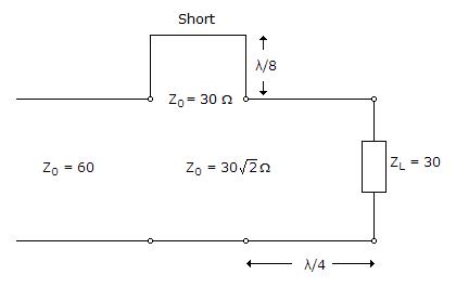
-
1.00 -
1.64 -
2.50 -
3.00
The logic function implemented by the following circuit at the terminal OUT is
-
P NOR Q -
P NAND Q -
P OR Q -
P AND Q
The input 3-dB frequency is :
-
100 Hz -
148 Hz -
100 kHz -
None
The transfer function of a zero-order-hold system is :
-
(l/s)(l + e-sT) -
(1/s)(1 - e-sT) -
1 - (l/s)e-sT -
1 + (1/s)e-sT
2's complement representation of abit number (one sign bit andmagnitude bits) is FFFF. Its magnitude in decimal representation is
-
0 -
1 -
32, 767 -
65, 535
System is :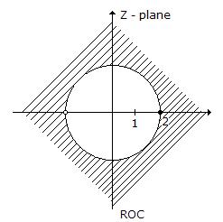
-
causal -
stable -
non causal -
anticausal
The Boolean function realized by the logic circuit shown is
-
F = Σm(0, 1, 3, 5, 9, 10, 14) -
F = Σm(2, 3, 5, 7, 8, 12, 13) -
F = Σm(1, 2, 4, 5, 11, 14, 15) -
F = Σm(2, 3, 5, 7, 8, 9, 12)
The Boolean function realized by the logic circuit shown is
-
F = Σm(0, 1, 3, 5, 9, 10, 14) -
F = Σm(2, 3, 5, 7, 8, 12, 13) -
F = Σm(1, 2, 4, 5, 11, 14, 15) -
F = Σm(2, 3, 5, 7, 8, 9, 12)
Find equivalent capacitance if each capacitance is 2 F.
-
5/12 F -
12/5 F -
6/5 F -
5/6 F
The feedback control system shown in the given figure represents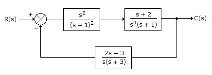
-
Type 0 system -
Type 1 system -
Type 2 system -
Type 3 system
Find RAB
-
2 Ω -
1.5 Ω -
3 Ω -
None of the above
The impulse response h(t) of a linear invariant continuous time system is given by h(t) = exp (- 2t) u(t), where u(t) denotes the unit step function. The output of this system to the sinusoidal input x(t) = 2cos(2t) for all time t, is
-
0 -
2-0.25 cos (2t - 0.125p) -
2-0.5 cos (2t - 0.125p) -
2-0.5 cos (2t - 0.25p)
AkHz carrier wave modulatedatHz is applied to a resonant circuit tuned to a carrier frequency and having Q =What is the degree of modulation after transmission through this circuit?
-
0.40 -
0.20 -
0.27 -
0.54
In the circuit shown, all the transmission line sections are lossless. The Voltage Standing Wave Ration (VSWR) on theline is
-
1.00 -
1.64 -
2.50 -
3.00
Find RL for maximum power transfer.
-
3 Ω -
1.125 Ω -
4.1785 Ω -
None of these
Find RL for maximum power transfer.
-
3 Ω -
1.125 Ω -
4.1785 Ω -
None of these
The logic function implemented by the following circuit at the terminal OUT is
-
P NOR Q -
P NAND Q -
P OR Q -
P AND Q
For a integrator circuit, Ri =KΩ, CF =μF. The input is a step dc voltage as shown below. Its output will be
Consider the Schmitt trigger circuit shown below. A triangular wave which goes from -V toV is applied to the inverting input of the op-amp. Assume that the output of the op-amp moves from +V to -V. The voltage at the non-inverting switches between
-
-12 V and +12 V -
-7.5 V and +7.5 V -
-5 V and +5 V -
0 V and 5 V
For the power amplifier circuit shown below, the maximum power dissipated by both output transistor is
-
9.66 W -
30.11 W -
31.66 W -
33.66 W
The region between a pin of parallel perfectly conducting planes of infinite extent is y and z directions is partially filled with a dielectric as shown below.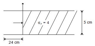
AGHz TE10 wave is incident on the air-dielectric interface. The VSWR at the interface is
-
- 2 -
2 -
0 -
1
The region between a pin of parallel perfectly conducting planes of infinite extent is y and z directions is partially filled with a dielectric as shown below.
AGHz TE10 wave is incident on the air-dielectric interface. The VSWR at the interface is
-
- 2 -
2 -
0 -
1
The Boolean function realized by the logic circuit shown is
-
F = Σm(0, 1, 3, 5, 9, 10, 14) -
F = Σm(2, 3, 5, 7, 8, 12, 13) -
F = Σm(1, 2, 4, 5, 11, 14, 15) -
F = Σm(2, 3, 5, 7, 8, 9, 12)
Find equivalent capacitance if each capacitance is 2 F.
-
5/12 F -
12/5 F -
6/5 F -
5/6 F
Find RL for maximum power transfer.
-
3 Ω -
1.125 Ω -
4.1785 Ω -
None of these
The impulse response h(t) of a linear invariant continuous time system is given by h(t) = exp (- 2t) u(t), where u(t) denotes the unit step function. The output of this system to the sinusoidal input x(t) = 2cos(2t) for all time t, is
-
0 -
2-0.25 cos (2t - 0.125p) -
2-0.5 cos (2t - 0.125p) -
2-0.5 cos (2t - 0.25p)
Find RL for maximum power transfer.
-
3 Ω -
1.125 Ω -
4.1785 Ω -
None of these
The logic function implemented by the following circuit at the terminal OUT is
-
P NOR Q -
P NAND Q -
P OR Q -
P AND Q
A power ofW is radiated from an isotropic radiator. The power radiated peer unit solid angle and the power density at a distance ofkm from the antenna is respectively
-
25 W, 10 W 
-

-
7.96 W, 0.08 μW -
0.08 μ W, 7.96 W
The feedback control system shown in the given figure represents
-
Type 0 system -
Type 1 system -
Type 2 system -
Type 3 system
The region between a pin of parallel perfectly conducting planes of infinite extent is y and z directions is partially filled with a dielectric as shown below.
AGHz TE10 wave is incident on the air-dielectric interface. The VSWR at the interface is
-
- 2 -
2 -
0 -
1
Find RAB
-
2 Ω -
1.5 Ω -
3 Ω -
None of the above
In the circuit shown, all the transmission line sections are lossless. The Voltage Standing Wave Ration (VSWR) on theline is
-
1.00 -
1.64 -
2.50 -
3.00
The logic function implemented by the following circuit at the terminal OUT is
-
P NOR Q -
P NAND Q -
P OR Q -
P AND Q
The region between a pin of parallel perfectly conducting planes of infinite extent is y and z directions is partially filled with a dielectric as shown below.
AGHz TE10 wave is incident on the air-dielectric interface. The VSWR at the interface is
-
- 2 -
2 -
0 -
1
A power ofW is radiated from an isotropic radiator. The power radiated peer unit solid angle and the power density at a distance ofkm from the antenna is respectively
-
25 W, 10 W
-
-
7.96 W, 0.08 μW -
0.08 μ W, 7.96 W
A power ofW is radiated from an isotropic radiator. The power radiated peer unit solid angle and the power density at a distance ofkm from the antenna is respectively
-
25 W, 10 W
-
-
7.96 W, 0.08 μW -
0.08 μ W, 7.96 W