Q.1.
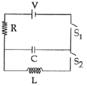
In an LCR circuit as shown below both switches are open initially.Now switch S1 is closed, S2 kept open. (q is charge on the capacitorand τ = RC is Capacitive time constant). Which of the followingstatement is correct?[ IIT Mains 2013]
-
20%
a) Work done by the battery is half of the energy dissipated in the resistor
-
33%
b) At t = τ, q = CV/2
-
47%
c) At t = 2τ, q = CV(1-e-2)
-
0%
d) At t = τ/2, q = CV(1-e-1)
Explanation
Q.2.
raph Q272) A thermal power plant produces electric power of 600 kW at 4000 V, which is to betransported to a place 20 km away from the power plant for consumers usage. It can betransported either directly with a cable of large current carrying capacity or by using acombination of step-up and step-down transformers at the two ends. The drawback ofthedirect transmission is the large energy dissipation. In the method using transformers, thedissipation is much smaller. In this method, a step-up transformer is used at the plant side sothat the current is reduced to a smaller value. At theconsumers end, a step-down transformeris used to supply power to the consumers at the specified lower voltage. It is reasonable toassume that the power cable is purely resistive and the transformers are ideal with a powerfactor unity. All the currents and voltages mentioned are rms values. Q272A) If the direct transmission method with a cable of resistance 0.4Ω km−1 is used, the powerdissipation (in%) during transmission is
-
17%
a) 20
-
17%
b) 30
-
25%
c) 40
-
42%
d) 50
Explanation
Q.3.
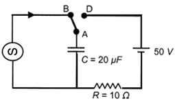
More than one correct option. At time t = 0, terminal A in the circuit shown in the figure is connected to B by a key andan alternating current I(t) = I0cos (ωt), with I0 = 1A and ω = 500 rad s−1 starts flowing init with the initial direction shown in the figure. At =7π/6ω, the key is switched from B to D. Now onwards only A and D are connected. A total charge Q flows from the battery tocharge the capacitor fully. If C = 20µF, R = 10 Ω and the battery is ideal with emf of 50V,identify the correct statement (s). [ IIT Advance 2014]
-
17%
a) Magnitude of the maximum charge on the capacitor before t=7π/6ω is 1 × 10⁻³ C.
-
33%
b) The current in the left part of the circuit just before t=7π/6ω is clockwise.
-
25%
c) Immediately after A is connected to D, the current in R is 10A.
-
25%
d) Q = 2×10⁻³ C.
Explanation

Q.4.
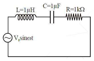
In the circuit shown, L = 1 μH, C = 1 μF and R = 1 kΩ. They are connected in series with an a.c. source V = V0 sin ωt as shown. Which of the following options is/are correct ? [ IIT Advance 2016]
-
20%
a) a) The frequency at which the current will be in phase with the voltage is independent of R.
-
30%
b) At ω ˜ 0 the current flowing through the circuit becomes nearly zero
-
30%
c) At ω >> 106 rad.s-1, the circuit behaves like a capacitor.
-
20%
d) The current will be in phase with the voltage if ω = 104 rad.s-1.
Explanation
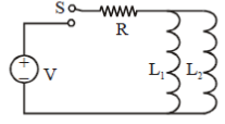
Q.5.
More than one correct option. A source of constant voltage V is connected to a resistance R and two ideal inductors L1 and L2 through a switch S as shown. There is no mutual inductance between the two inductors. The switch S is initially open. At t = 0, the switch is closed and current begins to flow. Which of the following options is/ are correct? [ IIT Advance 2017]
-
29%
a) The ratio of the current through L1 and L2 is fixed at all time (t > 0)

-
29%
b) After a long time, the current through L1 will be

-
29%
c) After a long time, the current through L2 will be
-
14%
d) At t=0, the current trough the resistance R is V/R
Explanation

Q.6.
The instantaneous voltages at three terminals marked X, Y and Z are given by Vx = V0 sinωt , Vy=V0 sin(ωt+2π/3) and Vz = V0 sin(ωt+4π/3) An ideal voltmeter is configured to read rms value of the potential difference between its terminals. It is connected between points X and Y and then between Y and Z. The reading(s) of the voltmeter will be … [ IIT Advance 2017]
-
25%
a)

-
38%
b)

-
12%
c) Independent of choice of terminal

-
25%
d)
Explanation

Q.7.
A wire loop is rotated in a magnetic field. The frequency of change of direction of the induced e.m.f. is [NEET 2013]
-
29%
a) Once per revolution
-
29%
b) Twice per revolution
-
29%
c) Four times per revolution
-
14%
d) Six times per revolution
Q.8.
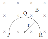
A thin semicircular conducting ring (PQR) ofradius 'r' is falling with its plane vertical in ahorizontal magnetic field B, as shown in figure.The potential difference developed across the ring when its speed is v, is … [ AIPMT 2014]
-
22%
a) πrBv and R is at higher potential

-
39%
b) 2rBv and R is at higher potential
-
28%
c) zero
-
11%
d) and P is at higher potential
Q.9.
A transformer having efficiency of 90% is working on 200V and 3kW power supply. If the current in the secondary coil is 6A, the voltage across the secondary coil and the correct in the primary coil respectively are
-
0%
a) 450 V, 13.5 A
-
20%
b) 600V, 15A
-
20%
c) 300V, 15A
-
60%
d) 450V, 15A
Q.10.
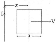
A conducting square frame of side ‘a‘ and a long straight wire carrying current I are located in thesame plane as shown in the figure. The frame moves to the right with a constant velocity ‘V‘. The emf induced in the frame will be proportional to :
-
33%
a)
-
0%
b)

-
50%
c)

-
17%
d)

Explanation


Q.11.
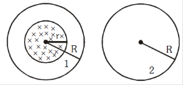
A uniform magnetic field is restricted within a region of radius r. The magnetic field changes with timeat a rate(dB)/dt. Loop 1 of radius R > r encloses theregion r and loop 2 of radius R is outside the region of magnetic field as shown in the figure below. Then the e.m.f. generated is …[NEET II -2016]
-
33%
a) in loop 1 and zero in loop 2

-
50%
b) in loop 1 and zero in loop 2

-
17%
c) Zero in loop 1 and zero in loop 2

-
0%
d) in loop 1 and zero in loop 2
Explanation
Q.12.
A long solenoid of diameter 0.1 m has 2×10⁴ turnsper meter. At the centre of the solenoid, a coil of 100turns and radius 0.01 m is placed with its axiscoinciding with the solenoid axis. The current in thesolenoid reduces at a constant rate to 0 A from 4 A in 0.05 s. If the resistance of the coil is 10π2Ω, the total charge flowing through the coil during this time is
-
33%
a) 32πµC
-
17%
b) 16µC
-
50%
c) 32µC
-
0%
d) 16πµC
Explanation

Q.13.
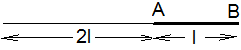
A metallic rod of length ‘l’ is tied to a string of length 2l and made to rotate with angular speedω on a horizontal table with one end of the string fixed. If there is a vertical magnetic field ‘B’ in the region, the e.m.f. induced across the ends of the rod is … [ IIT mains 2013]
-
43%
a)

-
0%
b)

-
29%
c)

-
29%
d)

Explanation
Q.14.
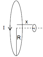
A circular loop of radius 0.3 cm lies parallel to a much bigger circular loop of radius 20 cm. The center of the small loop is on the axis of the bigger loop. The distance between their centers is 15 cm. If a current of 2.0 A flows through the smaller loop, then the flux linked with bigger loop is … [ IIT Mains 2017]
-
33%
a) 9.1 × 10⁻¹¹ weber
-
0%
b) 6 × 10⁻¹¹ weber
-
17%
c) 3.3 × 10⁻¹¹ weber
-
50%
d) 6.6 × 10⁻⁹ weber
Explanation
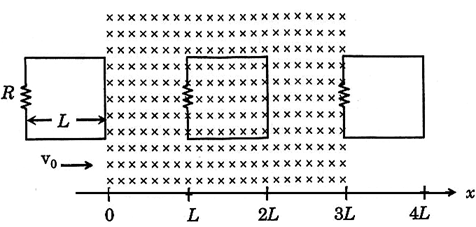
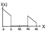
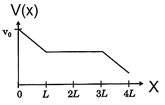
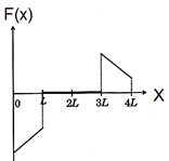
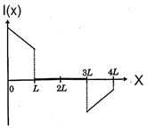
Q.15.
A rigid wire loop of square shape having side of length L and resistance R is moving along the x-axis with a constant velocity v0 in the plane of the paper. At t = 0, the right edge of the loop enters a region of length 3L where there is a uniform magnetic field B0 into the plane of the paper, as shown in the figure. For sufficiently large v0, the loop eventually crosses the region. Let x be the location of the right edge of the loop. Let v(x), I(x) and F(x) represent the velocity of the loop, current in the loop, and force on the loop, respectively, as a function of x. Counter-clockwise current is taken as positive. Which of the following schematic plot(s) is(are) correct? (Ignore gravity) [ IIT Advance 2016]
-
0%
a)
-
0%
b)
-
20%
c)
-
80%
d)
Explanation

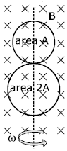
Q.16.
More than one correct option. A circular insulated copper wire loop is twisted to form two loops of area A and 2A as shown in the figure. At the point of crossing the wires remain electrically insulated from each other. The entire loop lies in the plane (of the paper). A uniform magnetic field B ⃗ points into the plane of the paper. At t = 0, the loop starts rotating about the common diameter as axis with a constant angular velocity ω in the magnetic field. Which of the following options is/are correct? [ IIT Advance 2017]
-
17%
a) The rate of change of the flux is maximum when the plane of the loops is perpendicular to plane of the paper
-
17%
b) The net emf induced due to both the loops is proportional to cos ωt
-
0%
c) The emf induced in the loop is proportional to the sum of the areas of the two loops
-
67%
d) The amplitude of the maximum net emf induced due to both the loops is equal to the amplitude of maximum emf induced in the smaller loop alone
Explanation