Q.1.
In an A.C. circuit, the resonance is obtained when [ Raj/.PET 1996]
-
58%
a) Z = R
-
25%
b) Z = ωL - (1/ ωC)
-
8%
c) L and C are in same phase
-
8%
d) The phase in C varies with source voltage
Q.2.
An L.C.R circuit is connected to a source of alternating current. At resonance, the applied voltage and current flowing through the circuit will have a phase difference of [ CBSE 1994]
-
0%
a) π/4
-
56%
b) zero
-
22%
c) π
-
22%
d) π/2
Q.3.
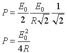
In an LR-circuit, the inductive reactance is equal to the resistance R of the circuit. An emf E = Eocosωt is applied to the circuit. The power consumed in the circuit is [ MPPMT 1997]
-
33%
a) Eo2 / R
-
33%
b) Eo2 / 2R
-
22%
c) Eo2 /4R
-
11%
d) Eo2 / 8R
Explanation
Q.4.
The current in resistance R at resonance is [ CPMT 1993]
-
0%
a) zero
-
20%
b) Minimum but finite
-
60%
c) Maximum but finite
-
20%
d) Infinite
Q.5.
The resistance of coil at frequency 104 Hz is 104 Ω, the reactance at 2×10⁴ Hz frequency will become [ Raj.PMT 1996]
-
11%
a) 104 Ω
-
56%
b) 2×10⁴ Ω
-
11%
c) 3×10⁷ Ω
-
22%
d) 4×10⁴ Ω
Q.6.
In pure resistance A.C. circuit the phase difference between current and voltage is [ Rj.PMT 1996]
-
62%
a) zero
-
12%
b) π/2
-
25%
c) -π/2
-
0%
d) π/4
Q.7.
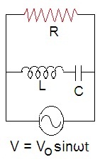
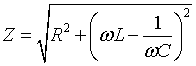
If resistance of 100Ω, inductance of 0.5 henry and capacitance of 10×10-6 fd are connected in series through 50 Hz AC supply, then impedance is : [ BHU 1995]
-
25%
a) 1.876 Ω
-
25%
b) 18.76Ω
-
50%
c) 187.6Ω
-
0%
d) 101.3Ω
Explanation
Q.8.
An alternating current of frequency f is flowing in a circuit containing a resistance R and a choke L in series. The impedance of the circuit is equal to [ MPPET 1999]
-
0%
a) R
-
50%
b) R +πfL
-
50%
c) √[ R2 +4π2f2L2]
-
0%
d) R/2πfL
Q.9.
A 10Ω resistance, 5mH coil and 10µF capacitor are joined in series. When a suitable frequency alternating current source is joined to this combination, the circuit resonates. If the resistance is halved, the resonance frequency [ MPPET 1995]
-
29%
a) is halved
-
29%
b) is doubled
-
43%
c) remain unchanged
-
0%
d) is quadrupled
Q.10.
The frequency for which a 5.0µF capacitor has a reactance of 1000Ω is given by [ MPPMT 1993]
-
29%
a) 1000/π cycles/sec
-
57%
b) 100/π cycles/sec
-
14%
c) 200 cycles/sec
-
0%
d) 5000 cycles/sec
Q.11.
In an AC circuit, a resistance of RΩ is connected in series with an inductance L. If phase angle between voltage and current be 45°, the value of inductive reactance will be [ MPPMT 1998]
-
29%
a) R/4
-
14%
b) R/2
-
43%
c) R
-
14%
d) can not found with the given data
Q.12.
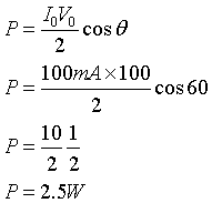
In an A.C circuit. V and I are given by V = 100sin100t volts and I = 100sin(100t + π/3) mA. The power dissipated in the circuit is [ MPPMT 1999]
-
0%
a) 104 watts
-
57%
b) 10 watts
-
0%
c) 2.5 watts
-
43%
d) 50 watts
Explanation
Q.13.
The root-mean-square value of an alternating current of 50hertz frequency is 10 ampere. The time taken by the alternating current in reaching from zero to maximum value and the peak value of current will be [ MPPMT 1993]
-
0%
a) 2×10⁻² sec and 14.14 amp
-
0%
b) 1×10⁻² sec and 7.07 amp
-
43%
c) 5×10⁻³ sec and 7.07 amp
-
57%
d) 5×10⁻³ sec and 14.14 amp
Q.14.
In a series resonant circuit, the a.c. voltage across resistance R, inductance L and capacitance C are 5V, 10V and 10V respectively. The a.c. voltage applied to the circuit will be [ CET 1994]
-
29%
a) 20 V
-
14%
b) 10 V
-
29%
c) 5 V
-
29%
d) 25 V
Q.15.
The impedance of a circuit consists of 3Ω resistance and 4Ω reactance. The power factor of the circuit is [ MPPMT 1994]
-
0%
a) 0.4
-
17%
b) 0.6
-
50%
c) 0.8
-
33%
d) 1.0
Q.16.
Same current is flowing in two alternating circuits. The first circuit contains only inductance and the other contains only a capacitor. If the frequency of the emf is increased the effect on the value of the current will be [ MPPMT 1993]
-
43%
a) Increase in first circuit and decrease in the other
-
14%
b) Increase in both circuits
-
0%
c) Decrease in both circuits
-
43%
d) Decrease in first circuit and increase in the other
Q.17.
At resonance, the source current is : [ Raj. 1996]
-
14%
a) minimum in series L-C-R circuit
-
43%
b) minimum in a parallel L-C-R circuit
-
29%
c) maximum in both series and parallel L-C-R circuits
-
14%
d) minimum in both series and parallel L-C-R circuits
Q.18.
An alternating voltage E( in volts) = 200√2sin(100t) is connected to a 1µf capacitor through an a.c. ammeter. The reading of the ammeter shall be [ MNR 1995]
-
20%
a) 10mA
-
50%
b) 20mA
-
30%
c) 40 mA
-
0%
d) 80mA
Q.19.
In an A.C circuit, containing an inductance and a capacitor in series, the current is found to be maximum when the value of inductance is 0.5 henry and of capacitance is 8µF. The angular frequency of the input A.C. voltage must be equal to [ CPMT 1991]
-
29%
a) 500
-
43%
b) 5×10⁴
-
14%
c) 4000
-
14%
d) 5000
Q.20.
A resistance R = 12Ω, inductance(L) = 2 henry and capacitance (C) = 5 mF are connected un series to an a.c. generator of frequency 50Hz [ CPMT 1998]
-
43%
a) At resonance, the circuit impedance is zero
-
14%
b) At resonance, the circuit impedance is 12Ω
-
29%
c) The resonance frequency of the circuit is (1/2)π
-
14%
d) The inductive reactance is less than the capacitance
Q.21.
An LCR circuit contains resistance of 100Ω and supply of 200 volts at 300 rad/sec angular frequency. If only capacitance is taken out from the circuit and the rest of the circuit is joined, current lags behind the voltage by 60°. If on the other hand only inductor is taken out, the current leads by 60° with the applied voltage. The current flowing in the circuit is [ CPMT 1998]
-
25%
a) 1 A
-
25%
b) 1.5A
-
50%
c) 2.0A
-
0%
d) 2.5A
Q.22.
An a.c circuit consists of an inductor of inductance 0.5H and a capacitor of capacitance 8µF in series. The current in the circuit is maximum when the angular frequency of a.c. source is [ CPMT 1986]
-
67%
a) 500 Hz
-
0%
b) 2×10⁵
-
17%
c) 4000 Hz
-
17%
d) 5000 Hz
Q.23.
An alternating current circuit consists of an inductance and a resistance in series. In this circuit [ CPMT 1986 ]
-
14%
a) The potential difference across and current in resistance leads the potential difference across inductance
-
29%
b) The potential difference across and current in resistance lags behind the potential difference across inductance by an angle π/2
-
14%
c) The potential difference across and current in resistance lags behind the potential difference across inductance by an angle π
-
43%
d) The potential difference across resistance lags behind the potential difference across inductance by an angle π/2
Q.24.
The average power dissipation in pure capacitance in A.C. us [ MPPMT 1998]
-
17%
a) ½ CV2
-
0%
b) CV2
-
0%
c) ¼ CV2
-
83%
d) zero
Q.25.
In non-resonant circuit, if the frequency is greater than the resonant frequency, the nature of circuit will be [ Raj PMT 1996]
-
0%
a) Resistive
-
14%
b) Capacitive
-
29%
c) Inductive
-
57%
d) All the above
Q.26.
The power factor in circuit connected to an A.C. power supply has a value which is [ MPPMT 1987]
-
0%
a) unity when the circuit contains an ideal inductance only
-
33%
b) unity when the circuit contains an ideal resistance only
-
50%
c) Zero when the circuit contains an ideal resistance only
-
17%
d) Unity when the circuit contains an ideal capacitance only
Q.27.
An LCR circuit containing R = 50Ω, L=1mH and C= 0.1µF. The impedance of the circuit will be minimum for a frequency of [ CET 1995]
-
50%
a) 105 / 2π s-1
-
17%
b) 106 / 2π s-1
-
33%
c) 2π×10-5 s-1
-
0%
d) 2π×10-6 s-1
Q.28.
In L-C-R series A.C. circuit, the phase angle between current and voltage is [ MPPMT 1998]
-
33%
a) Any angle between 0 and ± π/2
-
17%
b) π/2
-
33%
c) π
-
17%
d) Any angle between 0 and π/2
Q.29.
In pure inductive circuit, the current: [ MPPMT 1993]
-
17%
a) lags behind the applied emf by an angle π
-
17%
b) lags behind the applied emf by an angle π/2
-
33%
c) leads the applied emf by an angle π/2
-
33%
d) and applied emf are in same phase
Q.30.
Using an AC voltmeter, the potential difference in the electrical line in a house is read to be 234 Volts. IF the line frequency is known to be 50 cycles per second, the equation for the line voltage is [ MPPMT 1987]
-
0%
a) V = 165sin(100πt)
-
60%
b) V = 331sin(100πt)
-
20%
c) V = 234sin(100πt)
-
20%
d) V = 440sin(100πt)