Q.1.
In the following circuit, the value of Norton’s resistance between terminals a and b are ___________
- a) RN = 1800 Ω
- b) RN = 270 Ω
- c) RN = 90 Ω
- d) RN = 90 Ω
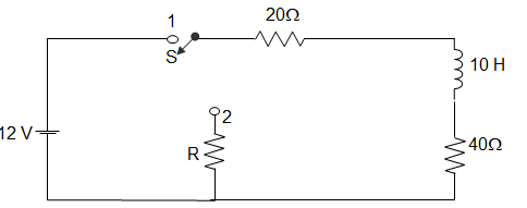
Q.2.
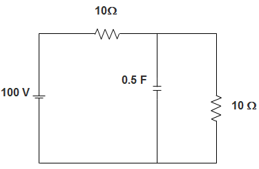
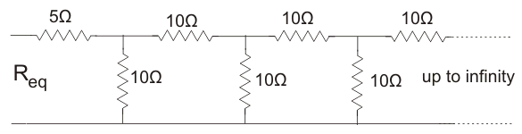
For the circuit shown in figure below, the value of Norton’s resistance is _________
- a) 100 Ω
- b) 136.4 Ω
- c) 200 Ω
- d) 272.8 Ω
Q.3.
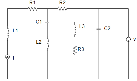
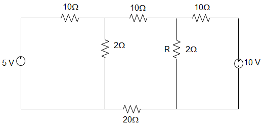
In the figure given below, the value of Resistance R by Norton’s Theorem is ___________
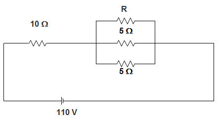
- a) 40
- b) 20
- c) 50
- d) 80
Q.4.
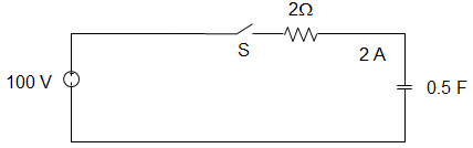
In the figure given below, the Norton Resistance, as seen at the terminals P-Q, is given by __________
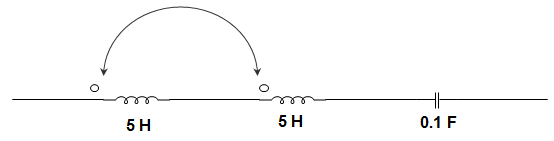
- a) 5 Ω
- b) 7.5 Ω
- c) 5 Ω
- d) 7.5 Ω
Q.5.
In the circuit given below, it is given that VAB = 4 V for RL =kΩ and VAB = 1 V for RL = 2kΩ. The value of Norton resistance for the network N is ____________
- a) 16 kΩ
- b) 30 kΩ
- c) 3 kΩ
- d) 50 kΩ
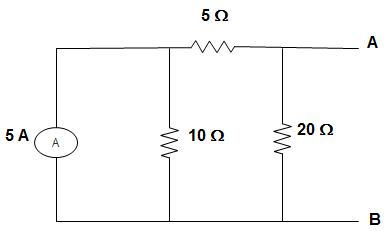
Q.6.
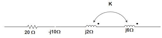
For the circuit given below, the Norton’s resistance across the terminals A and B is _____________
- a) 5 Ω
- b) 7 kΩ
- c) 1.5 kΩ
- d) 1.1 kΩ
Q.7.
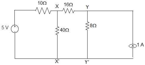
A circuit is given in the figure below. The Norton equivalent as viewed from terminals x and x’ is ___________
- a) 6 Ω and 1.333 A
- b) 6 Ω and 0.833 A
- c) 32 Ω and 0.156 A
- d) 32 Ω and 0.25 A
Q.8.
For the circuit given in figure below, the Norton equivalent as viewed from terminals y and y’ is _________
- a) 32 Ω and 0.25 A
- b) 32 Ω and 0.125 A
- c) 6 Ω and 0.833 A
- d) 6 Ω and 1.167 A
Q.9.
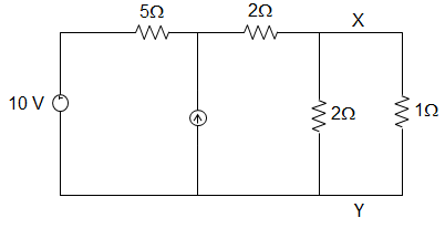
In the figure given below, the power loss in 1 Ω resistor using Norton’s Theorem is ________
- a) 9.76 W
- b) 9.26 W
- c) 10.76 W
- d) 11.70 W
Q.10.
The value of RN from the circuit given below is ________
- a) 3 Ω
- b) 1.2 Ω
- c) 5 Ω
- d) 12.12 Ω
Q.11.
The current I, as shown in the figure below, is ________
- a) 3 A
- b) 2 A
- c) 1 A
- d) 0
Q.12.
While computing the Norton equivalent resistance and the Norton equivalent current, which of the following steps are undertaken?
- a) Both the dependent and independent voltage sources are short-circuited and both the dependent and independent current sources are open-circuited
- b) Both the dependent and independent voltage sources are open-circuited and both the dependent and independent current sources are short-circuited
- c) The dependent voltage source is open-circuited keeping the independent voltage source untouched and the dependent current source is short-circuited keeping the independent current source untouched
- d) The dependent voltage source is short-circuited keeping the independent voltage source untouched and the dependent current source is open-circuited keeping the independent current source untouched